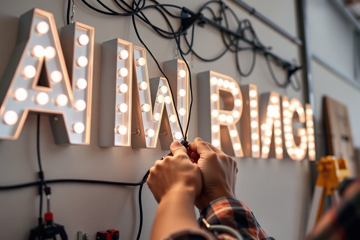
How to Wire an Illuminated Sign Safely: A Complete Step-by-Step Guide
Figuring out how to wire an illuminated sign safely starts with knowing the right connection method and following electrical codes like NEC Article 600. Use low-voltage wiring for easier handling and safer installation. Begin by selecting the proper power supply and trimming your electroluminescent wire to fit without excess length.
Key Takeaways
- Always cut EL wire leaving about 2 inches extra for secure connections and easy adjustment.
- Feed power wires through interior to exterior walls using a 1/8-inch drill hole for neat installation.
- Use parallel wiring for lights spanning over 20 feet or multiple sign locations to maintain consistent power.
- Connect low-voltage wires carefully to avoid overcrowding wire nuts or phoenix connectors with too many wires.
- Confirm your sign meets UL 48 certification and follows applicable local electrical codes for safety compliance.
- Install the power supply in an accessible, dry location to protect connections and simplify maintenance.
What Does Wiring an Illuminated Sign Involve?
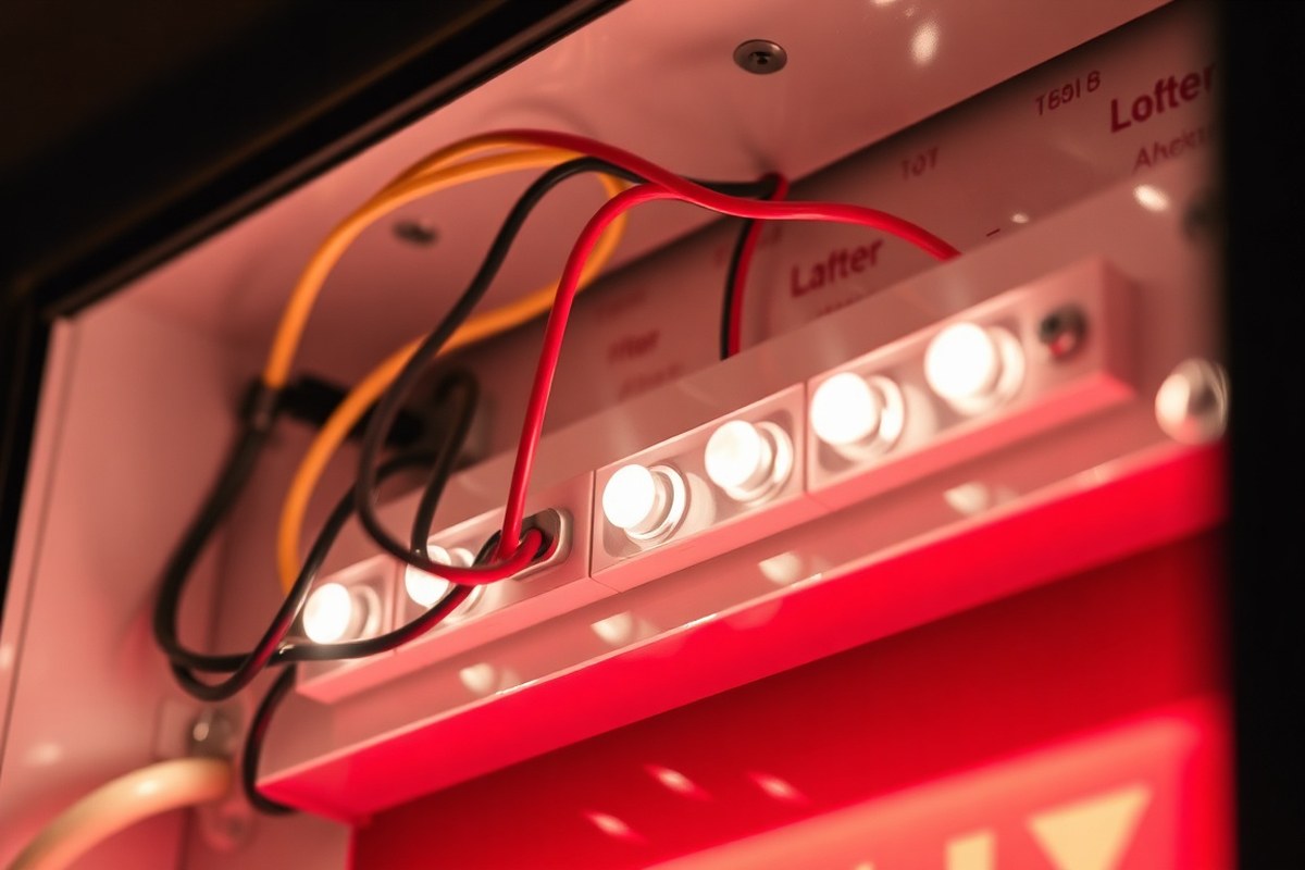
Wiring an illuminated sign involves connecting several key electrical components to safely channel power and light up the sign. At the core, the system includes the light source, usually LED modules, neon tubes, or electroluminescent (EL) wire, a power supply or transformer, wiring to carry current, and connectors that join these elements. The power supply converts line voltage (120V or 240V AC in the US) into the proper voltage and current type for the lighting. Proper wiring ensures electricity flows smoothly from the power source to the lights and back, completing a circuit that activates the illumination.
The electricity flow starts from the main power connection, moves through a transformer or power supply that lowers or modifies the voltage, then travels along wires to the individual lighting elements. For LED signs, which operate on low-voltage DC power, wiring involves connecting positive and negative leads to each LED module. Neon signs require high-voltage AC power, so wiring includes insulated cables rated for high voltage, running from a neon transformer to the glass tubes. EL wire uses a small inverter that converts DC from batteries or an adapter to AC at low voltage, with two wires: power and ground, connected at the inverter end.
Differences in wiring techniques also relate to the light source type. LEDs generally require multiple parallel circuits with low-voltage wires, often 12V or 24V DC, arranged to distribute current evenly. Wire gauge size must match current load, typically 18 to 16 gauge for small signs. Neon wiring needs thicker, high-insulation cables rated for several thousand volts, connected directly to a neon transformer mounted nearby but housed properly to prevent electrical hazards. EL wire wiring is simpler but requires an inverter for AC power, and the wiring runs from the inverter output to the EL wire leads, often hidden behind the sign face.
Safe and lasting wiring hinges on using components certified to UL 48 or CSA C22.2 standards for electric signs. These standards cover electrical safety, fire resistance, and environmental durability, especially for outdoor signs exposed to moisture. Wires must be properly stripped and secured with suitable connectors; overcrowding wire nuts or using unapproved splices can create fire or short hazards. Excess wiring should be coiled neatly and concealed inside the sign’s raceway or backer to prevent mechanical strain or exposure to the elements.
Depending on the sign type, wiring can range from simple battery-powered EL wire setups costing around $30, $50 per kit to more complex LED channel letters that may require custom power supplies and professional-grade wiring materials priced from $100 to several hundred dollars. Well-executed wiring delivers even illumination with no flickering or dead sections. Faulty wiring often shows as dim or unlit areas, buzzing transformers, or tripped breakers, indicating loose connections, improper wire gauge, or moisture intrusion. Ensuring the right wiring approach and following electrical codes leads to a durable, attractive illuminated sign safely powered for years.
Essential Tools and Materials for Wiring Your Sign
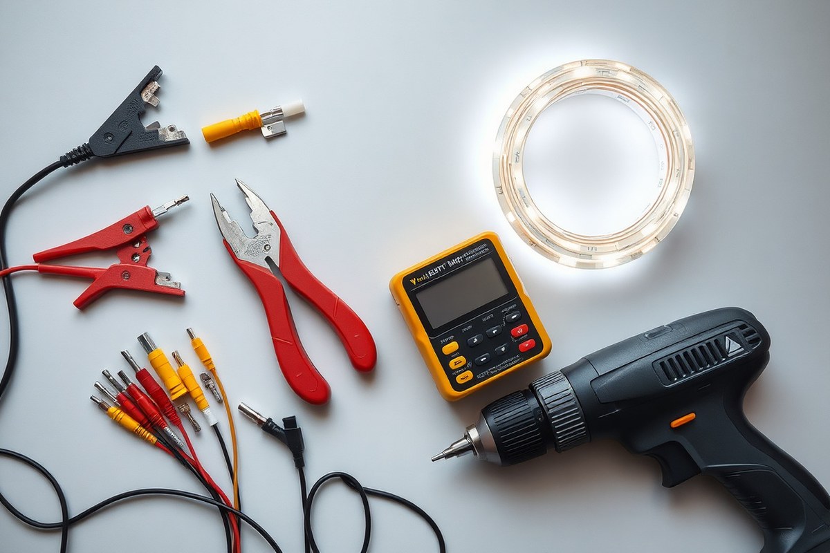
To wire an illuminated sign successfully, gather the right tools and materials upfront. Using proper wiring tools ensures safety and a neat, reliable installation. Wire choice impacts both performance and longevity, while correct power supplies and connectors maintain electrical integrity. Your wiring kit should include:
- Wire strippers and cutters suited for 22 to 16 gauge wire
- Insulated needle-nose pliers for precise manipulation
- Voltage tester to verify power presence and avoid shocks
- Wire connectors compatible with sign wire gauge and type
- Multimeter to measure voltage, current, and continuity
- Electrical tape or heat shrink tubing for insulation
- Mounting clips or cable ties to secure wiring neatly
Wire type matters because illuminated signs commonly use low-voltage DC power, often 12V or 24V from LED or electroluminescent (EL) sources. Using 18 to 22 gauge stranded copper wire provides flexibility and sufficient current capacity for typical letter lighting runs under 50 feet. For longer distances or higher current, 16 gauge may be necessary to prevent voltage drop and dimming.
Power supplies must match your sign’s voltage and wattage requirements exactly. A typical LED channel letter may require 12V DC at 1 amp or less. Larger signs need multiple supplies, each allocated about 1 amp to handle their section. Select UL-listed power supplies designed for sign use to meet electrical codes and improve safety.
When connecting wires, use connectors that perfectly fit your wire gauge and type; improper connectors can cause loose connections and failures. Common connector types include insulated butt splices, crimp connectors, and push-in quick connectors. Ensure secure fastening by using a crimp tool rated for your connectors.
Always verify power is off before handling wires and use wire connectors matched to the wire gauge to avoid electrical hazards and poor connections.
By preparing these tools and materials to the right specs, you create a solid foundation for your illuminated sign’s wiring. This prevents most installation issues and supports a safe, bright outcome that meets quality and code standards.
How to Connect Low-Voltage Wiring to the Sign
To wire low-voltage LEDs or EL wire to the power supply, feed the wire carefully from inside to outside, prepare and strip the wires correctly, then make secure connections using wire connectors or solder and heat shrink. Prevent voltage drop by using stranded wire, wiring in parallel for larger signs, and ensuring tight, even connections.
Preparing and Stripping Wires Properly
Start by locating the low-voltage wire that comes from the back of the sign. This wire will usually be stranded, which provides better contact and reduces voltage drop. Fish this wire through the wall or mounting surface, from the interior to the exterior, keeping it away from sharp edges that could damage the insulation.
Use a wire stripper to remove about ⅜ to ½ inch of insulation from the end of each wire. Stripping too little can make a weak connection, while stripping too much exposes excess wire that could short circuit. For best results, use a wire stripper sized for 18- to 22-gauge stranded wire, which is common for low-voltage LED signs.
Making Secure Wire Connections and Solder Joints
Proper connections prevent loose contacts and voltage drop. For connecting wires, choose one of these methods:
- Use wire connectors designed for low-voltage connections. Choose rated connectors that fit your wire gauge and avoid overloading them with multiple wires.
- Solder wires together and cover the joint tightly with heat shrink tubing to prevent exposure to moisture and corrosion.
- Use terminal blocks or wire splitters to join multiple wires in parallel safely, especially for signs with multiple LED segments.
Ensure every strand of the stranded wire makes contact by twisting strands neatly before joining. When soldering, heat the wire evenly and apply solder until it flows smoothly. Slide heat shrink tubing over the joint before soldering, then shrink it in place with a heat gun at around 250°F (120°C).
Routing and Concealing Wires Behind the Sign
Run the wires neatly behind the sign or inside any mounting enclosure designed for the power supply. Secure wires periodically with cable clips or zip ties to prevent strain on the connections. Avoid tight bends or kinks that can damage internal wiring.
Feed wires through a drilled hole or a factory-installed grommet to pass from interior to exterior spaces. Seal around the hole with silicone caulk to prevent water and pests from entering. Position the power supply housing in a concealed location near the sign, but accessible for maintenance.
Connecting lights to the controller or power supply using parallel wiring helps minimize voltage drop, especially on extended runs or with several light segments. Aim to keep wire lengths short to preserve consistent voltage and avoid dimming issues.
- Locate the low-voltage wire exiting the sign’s back and plan the interior-to-exterior feed path.
- Fish the wire through the wall or mounting surface, protecting it as needed from sharp edges.
- Strip about ⅜ to ½ inch of insulation from wire ends using a suitable wire stripper.
- Twist stranded wires neatly and connect using wire connectors, solder joints, or terminal blocks.
- When soldering, place heat shrink tubing on one wire before making the connection, then apply heat to shrink it over the joint after soldering.
- Secure wires behind the sign with clips or ties, avoiding sharp bends and strain.
- Seal any holes used to route wires with silicone caulk to protect against moisture.
- Plug in the power supply adapter inside and test the sign for even illumination and stable voltage.
Installing the Power Supply and Making AC Connections
Install the power supply near a dedicated electrical source in a dry, ventilated area away from direct sunlight and excessive heat. Connect the unit to 120-277VAC power following local electrical codes, using the correct wiring, breakers, and grounding methods to ensure safety and code compliance. Always use power supplies that meet UL 48 certification or an equivalent standard for illuminated signs.
Selecting an Appropriate Power Supply
Choose a power supply rated for the total wattage of your illuminated sign, including some overhead capacity to allow for minor surges and future expansion. Power supplies designed specifically for illuminated signs typically provide constant voltage and protect against overcurrent, short circuits, and thermal overload.
Verify the power supply has UL 48 or equivalent product certification, as this confirms the unit meets national safety standards required for outdoor or commercial sign use. This certification helps ensure product reliability and compliance with local electrical codes.
Mounting and Securing the Power Supply Housing
Install the power supply inside a weatherproof, ventilated enclosure suitable for the installation location. The enclosure should be mounted close to the sign and power source, with secure fasteners on a stable surface such as an interior wall or an approved mounting bracket.
Leave at least 6 inches of clearance around the housing for heat dissipation and inspection access. Avoid mounting in locations exposed to direct sunlight, rain, or extreme temperatures to prolong the life of the power supply. Use corrosion-resistant screws or bolts suitable for the mounting surface.
Connecting AC Input with Proper Breakers and Wiring
Use a dedicated circuit breaker sized according to the power supply’s current rating found on its label, typically between 5A and 20A for most illuminated sign supplies. The breaker should be installed in the building’s main electrical panel or a sub-panel nearest the sign location.
The AC wiring must follow local electrical and fire codes, using copper conductors sized to handle the expected load with at least a 125% safety margin. Use conduit or approved cable protection where exposed, and ground the power supply chassis to prevent electrical shock hazards. Follow these steps to safely connect the AC input:
- Turn off the main power supply before starting any wiring to avoid shock hazards.
- Mount the power supply enclosure in the selected location following mounting guidelines.
- Run conduit or cable from the dedicated circuit breaker panel to the power supply enclosure.
- Strip and connect the hot, neutral, and ground wires to the terminal block inside the power supply according to the manufacturer’s wiring diagram.
- Secure all wire connections with wire nuts or terminal screws, ensuring no bare wires are exposed outside of terminals.
- Double-check the circuit breaker size matches the power supply rating and confirm the panel is properly labeled.
- Restore power and use a multimeter to verify the correct AC voltage is present at the power supply input.
- Test the sign’s illumination and inspect all wiring for heat, unusual smells, or loose connections.
Avoiding Common Wiring Mistakes and How to Fix Them
Voltage drop and power loss often happen when wire connectors are overloaded or wires are too long and undersized for the load. Using wire nuts or power distribution blocks with more conductors than they are rated for creates loose or heating connections. To avoid this, do not exceed the connector’s capacity; for example, standard wire nuts typically handle two to three wires. Overloading them raises resistance, wasting energy and risking overheating.
Wire length matters because longer wires increase resistance, causing voltage drop that dims the sign. Use wires sized at least 14 AWG for runs under 50 feet and upgrade to 12 AWG if the wire length exceeds 50 feet, depending on your sign’s wattage. Always measure the distance from the power supply to the sign and back, then choose the wire gauge accordingly. Insufficient supply wire length leads to tight bends or stretched wires, risking damage and poor connections. Here are the most common wiring errors with practical fixes:
- Overloading wire connectors: Use only the number of wires that fit comfortably; split large wire bundles across multiple connectors.
- Using undersized wire for long runs: Upgrade to thicker wire (lower AWG number) to reduce voltage drop.
- Leaving wires twisted or dirty: Strip insulation cleanly and straighten wires before twisting or inserting in connectors.
- Failing to support wire bundles: Use cable ties or clips to prevent strain on connections and reduce movement that causes wear.
- Poor ground connections: Connect ground wires firmly to grounding screws or grounding bus bars to avoid electrical noise and hazards.
- Not allowing access for maintenance: Route wires so connectors are reachable without removing parts of the sign.
- Ignoring manufacturer’s wire type recommendations: Use rated cable and connectors designed for outdoor or wet locations if the sign is outside.
Each correction supports performance and safety. For example, ensuring wires are clean and straight before making connections minimizes resistance and heat buildup. Properly rated connectors and wire sizes prevent overheating and voltage drop, which keeps your sign bright and prevents damage.
Always double-check the connector ratings and wire gauges before final assembly to avoid costly rework and potential fire hazards.
Addressing these errors can take an afternoon and may add $10 to $50 for extra wire or connectors, but it protects your investment. The result is a clean installation that stays bright, safe, and ready for routine maintenance without rewiring headaches.
Safety Precautions When Wiring Illuminated Signs
Always wear insulated gloves and safety glasses when wiring illuminated signs to protect against electric shock and debris. Use tools with insulated handles rated for at least 1000 volts, such as wire strippers and screwdrivers designed for electrical work. Non-conductive footwear helps reduce the risk of grounding yourself. These precautions reduce injury risk during wiring by preventing accidental contact with live parts.
Before starting any wiring work, disconnect power at the circuit breaker or disconnect switch dedicated to the sign circuit. Confirm power is off using a non-contact voltage tester or multimeter. Do not rely on just switching off a wall switch or unplugging an adapter, as NEC Article 600 requires a disconnecting means that isolates the sign’s power supply safely and completely. Label the disconnect clearly for future maintenance safety.
To meet UL 48 standards, select signs and components tested and listed for electric sign use. UL 48 focuses on the safety of the sign’s construction and operation, including wiring and internal components. NEC Article 600 sets the requirements for installation methods, including conductor sizing, grounding, and the installation of disconnect means. Wiring must be done according to both standards to ensure you avoid hazards such as overheating or electrical faults.
All wiring should use cables rated for outdoor use if the sign is exterior, or wet location rated cables. Secure wiring inside the sign enclosure and feed cables through approved connectors or bushings to prevent abrasion. Ground the sign metal parts properly to the building grounding system to reduce shock risks if a fault occurs. NEC Article 600 requires that electric signs have a disconnecting means within sight or lockable if remote.
Verify local codes that apply in addition to NEC Article 600 and UL 48, since some jurisdictions adopt amendments or add restrictions. For example, some areas require weatherproof enclosures or specific conductor types that affect your wiring choices. Following all requirements avoids inspection failures and potential liabilities.
Expect to invest in quality electrical materials and safety gear, which may raise costs slightly compared to basic hardware store supplies. This investment avoids costly damage from electrical faults and protects both you and the people viewing the sign. Perform final tests to ensure no voltage is present before touching wires and that the disconnect works correctly once wiring is complete.
Best Practices to Conceal and Secure Wiring
Concealing and securing wiring for an illuminated sign ensures a clean, professional look and protects the electrical components from damage. You should route wires behind the sign or inside walls whenever possible. This approach hides cables from view while maintaining easy access points for future servicing. Use existing conduit paths or create small channels inside walls with a drywall saw. When running wires behind a sign mounted on a building exterior, place them inside weatherproof raceways or conduit to shield against environmental exposure.
Choose clips and conduits designed for outdoor or commercial use. UV-resistant plastic clips and metal conduit are common choices. Clips should be spaced every 12 to 18 inches to keep wires tight and prevent sagging. When wiring passes through or along a wall, use flexible conduit to protect against abrasion and water infiltration. For each wire bundle, separate power and low-voltage cables to avoid interference and overheating.
- Use surface-mounted raceways for visible but protected wiring runs.
- Install wire clips at regular intervals (12-18 inches) for neat runs.
- Use flexible conduit through walls or tight spaces for protection.
- Color-code or label wires to simplify future troubleshooting.
- Leave access panels or removable covers near connections for maintenance.
- Do not over-tighten clips; allow slight wire movement to reduce stress.
Maintaining wiring access is as important as hiding the wires themselves. Install removable access panels where wiring connects to the power supply or within the sign housing. This lets you inspect or replace components without removing the entire sign. Wires running inside walls should have junction boxes with cover plates installed. These boxes keep connections secured and accessible while meeting common electrical code requirements. For exterior signs, ensure weatherproof covers are rated for outdoor use to prevent moisture damage.
Good results look like straight, neatly bundled wiring with no loops or tangles. Wiring should not sag or pull tight against clip anchors. Over time, poorly secured wiring can wear insulation or loosen connections, causing shorts or outages. Investing a few dollars per clip and conduit section upfront saves costly repairs and maintains your sign’s polished appearance. Keep all wiring runs clean and organized to reflect the professionalism your illuminated sign is meant to convey.
When to Hire a Professional for Wiring Illuminated Signs
Deciding whether to hire a licensed professional for wiring an illuminated sign depends on several factors including the complexity of the electrical work, local regulations, and your own experience level. Basic wiring of low-voltage components inside a sign that plugs into a standard outlet often can be handled by experienced DIYers. However, any work that involves high-voltage AC connections, permanent wiring, or integrating the sign into existing building circuits typically requires a licensed electrician. This is not only to ensure safe, code-compliant installation but also to avoid voiding warranties or risking damage to your property.
Local permits and inspections play a key role in this decision. Most commercial zones mandate permits for illuminated signs, especially when the installation affects permanent electrical systems or is mounted outdoors. These permits ensure the work meets safety and zoning codes. The requirements vary widely by state, city, and even neighborhood, so your first step should be checking with your municipal building or electrical department. If a permit and inspection are required, chances are the wiring needs to be performed or at least verified by a licensed professional.
You can use a simple decision rule: if your wiring project involves permanent electrical connections beyond plugging into an outlet or if it will require a permit or inspection, hire a licensed electrician. Also, if you are not comfortable working safely with high-voltage wiring, bringing in a pro avoids hazards like electrical shock or fire. Licensed installers also ensure the sign is securely mounted and level, preventing costly repairs later.
Finding a qualified installer can start with your local electrical contractors association or sign manufacturers certified through programs such as UL’s General Coverage program. Many areas provide online databases of licensed electricians or sign installers who meet code standards. For example, you can contact your city’s permitting office or visit its website to get recommended professionals familiar with local sign installation requirements. You can also inquire where you purchased your custom illuminated sign to get referrals for installers who understand the specific wiring needs of your product.
Hiring a licensed professional often costs between $75 and $150 per hour depending on the region, with a typical illuminated sign installation taking several hours. This investment covers not just the labor but also obtaining permits and passing inspections, which ultimately protects your business and reduces liability. Poor wiring without proper permits can lead to fines or having to remove the sign entirely.
Always verify your installer’s license and check for recent work or references to ensure they are qualified to handle illuminated sign wiring in your local area.
Maintaining Wiring and Testing the Sign After Installation
Testing wiring and maintaining your illuminated sign helps ensure consistent performance and extends its lifespan. Regular checks catch issues like voltage drops or loose connections early. Performing simple tests with a multimeter and keeping wiring clean prevents failures and costly repairs over time.
Using a Multimeter to Check Voltage and Continuity
Testing with a multimeter verifies that wiring supplies the correct voltage and that electrical pathways are complete. Check voltage after installation to confirm power matches the sign’s rating, usually listed on the transformer. Continuity testing helps detect breaks or shorts in wiring before they cause problems.
- Turn off power to the sign at the circuit breaker or disconnect switch.
- Set the multimeter to the appropriate voltage range (usually 0, 30 volts DC for LED signs).
- Turn the power back on and carefully touch the multimeter probes to the sign terminals, noting the voltage reading.
- Set the multimeter to continuity mode.
- With power off, test each wiring segment by placing probes at each end to ensure a continuous connection.
- Check for voltage drops by measuring voltage at the power supply and at the farthest LED group; a difference over 0.5 volts signals possible wiring issues.
Results showing proper voltage close to the transformer output and continuous circuit readings indicate good wiring condition. Voltage drops or no continuity require inspecting connectors, crimps, or cables for damage or loose contacts.
Cleaning and Inspecting Wiring Junctions
Over time, dirt, moisture, and oxidation can degrade connections in wiring junction boxes. Inspecting and cleaning them keeps electrical contacts corrosion-free and reduces the risk of shorts or open circuits. Outdoor signs must especially protect wiring with weatherproof enclosures.
Inspect wiring junctions every 6 to 12 months by opening access panels and checking for discoloration, loose wires, or moisture buildup. Clean corrosion using a soft brush and approved electrical contact cleaner. Tighten any loose connections using the proper tools, avoiding overtightening that can damage connectors.
Routine Power Cycling and Troubleshooting
Power cycling the sign, turning it off and on, helps detect intermittent issues caused by wiring faults or component fatigue. Frequent power interruptions may reveal flickering lights or failure points that continuous operation conceals.
Perform a power cycle test monthly by switching off the sign for five minutes, then restoring power and observing the lighting behavior. Flickering, dimming, or delayed illumination signals possible wiring degradation or power supply problems that need further investigation.
If issues arise, isolate problematic wiring sections by selectively disconnecting parts of the circuit and testing voltage and continuity. This diagnostic approach helps pinpoint damaged cables or connectors requiring replacement, maintaining your sign’s reliability over time.
Step-by-Step Action Plan for Wiring Your Illuminated Sign
Follow these steps to wire your illuminated sign safely and effectively, knowing each part is done right before moving on.
- Before you start: Gather all essential tools and materials listed for the job. Confirm you have the correct wire gauge and power supply suitable for your sign’s voltage to avoid safety issues.
- Day 1: Connect the low-voltage wiring to the sign terminals, ensuring a snug and secure fit. Check continuity with a multimeter to verify proper connections.
- Day 2: Install the power supply in a dry, accessible location. Connect the AC wires according to your local electrical codes, ensuring all connections are tight and insulated.
- Day 3: Test the sign by powering it on briefly. Look for consistent lighting without flicker or heat at connection points to confirm proper wiring.
- Day 4: Conceal and secure all wiring using cable clips, conduits, or channels to prevent damage and create a clean look. Check that wires are not pinched or strained.
- Week 1: Reinspect all wiring for signs of wear or loose connections after the sign has run for a few hours. Tighten or adjust as needed.
- After 2 weeks: Perform a second functional test and maintenance check. Replace any worn components or call a professional if issues persist.
Frequently Asked Questions
How to Wire an Illuminated Sign?
Connect the power wire to the adapter, ensuring proper polarity and secure connections. Use appropriate wire types and follow the sign’s wiring diagram for safety and longevity.
What Type of Wire Is Best for Outdoor Illuminated Signs?
Use weather-resistant, outdoor-rated wires like THHN or UF cables. These withstand moisture and temperature changes, preventing shorts and extending sign life.
Can I Use LED Strips Instead of Traditional Bulbs Inside My Sign?
Yes, LED strips are energy-efficient and easier to wire but check voltage compatibility with your power supply. They provide even illumination and last longer than bulbs.
How Do I Test My Sign’s Wiring After Installation?
Use a multimeter to check voltage and continuity on all connections. Testing prevents shorts and ensures the sign lights evenly before final mounting.
What Power Supply Rating Is Needed for an Illuminated Sign?
Match the power supply voltage and amperage to your sign’s specifications, usually found on the product label. Oversizing can waste energy; undersizing risks failure.
Are Battery-Powered Wires Practical for Commercial Signs?
Battery-powered EL wire kits suit small, portable signs but aren’t ideal for large or permanent commercial signs due to limited run time and brightness.
The Bottom Line
Wiring an illuminated sign requires careful attention to detail, safety, and inspection steps to keep your installation reliable. Start by testing each element independently, then monitor your sign regularly after installation to catch problems early. Taking these actions will help maintain a bright, safe, and effective display that adds to your business presence or project.