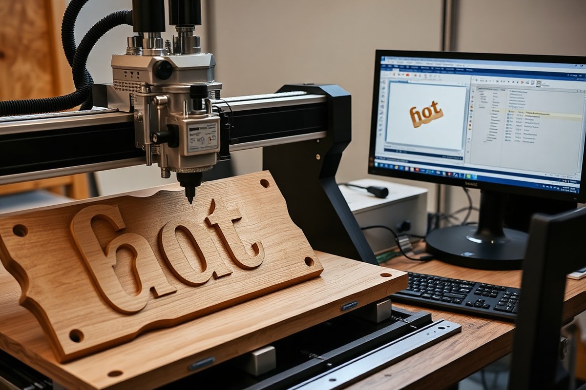
How to Use VCarve for CNC Projects: Complete Step-by-Step Guide
How to use VCarve starts with understanding its core function: creating detailed CNC toolpaths from vectors and 3D models. You set up your project file with precise dimensions and select the right toolpaths to match your design. Begin by defining your material size and machine setup to ensure accurate cuts every time.
Key Takeaways
- Set your project units and material size correctly before importing or creating any design elements in VCarve.
- Start with simple 2D toolpaths to build confidence in controlling cut depth and tool movement.
- Use a pass depth of about 3 mm for wood, typically half the diameter of your cutter, to avoid overloading tools.
- Add ramps at a 30-degree angle in toolpaths to reduce tool wear and improve cut quality on pockets and slots.
- For finishing passes, set stepover to 8, 10% of your tool’s diameter for smooth, decorative relief surfaces.
- Scale 3D files to match your desired part size before calculating toolpaths to ensure proper fit and detail.
What Is VCarve and How Does It Work?
VCarve is a software program designed to create detailed toolpaths for 3-axis CNC machines, including those equipped with an optional rotary axis. It helps you take your design files and turn them into instructions called g-code, which your CNC machine uses to cut or carve materials. The software supports both 2D and 3D projects, making it suitable for anything from simple signs and flat artworks to complex relief carvings and sculpted components.
The main purpose of VCarve is to simplify the process of preparing designs for CNC machining. You start by importing or creating vector drawings or 3D models directly within the software. After setting your material size and machine limits, VCarve generates toolpaths, precise routes that the cutting tool follows. These include standard 2D toolpaths for cutting profiles, pockets, and engraving, as well as 3D roughing and finishing toolpaths for relief carving based on imported STL files or components. The software also offers a unique feature to “wrap” flat designs around cylinders, enabling rotary axis machining for projects like custom cups or tubes.
Using VCarve involves a clear workflow. Begin by defining your job setup, which sets the stock size and material thickness. Then import or design your vectors or 3D models. Next, choose the appropriate toolpaths and set cutting parameters such as tool size, cutting depth, and speeds. VCarve’s interface groups commands into menus like File, Edit, Model, Machine, and Toolpaths to guide you through these steps. After setting paths, use the built-in simulation tools to preview the machining process and catch mistakes before you cut. This reduces the chance of wasting materials or damaging tools. Once satisfied, export the g-code tailored to your CNC machine’s post-processor, ensuring measurements like inches or millimeters match your setup.
VCarve is best suited for woodworking, sign making, cabinetry, furniture design, and intricate 3D relief projects. Its combination of straightforward tools and advanced 3D capabilities lets beginners handle simple cuts while providing experienced users options to create professional-grade carvings. Licensing typically ranges around a few hundred dollars, reflecting its strong features without the complexity of industrial-only software. Getting good results means carefully scaling models, choosing correct tools, and using VCarve’s simulation to avoid costly errors. Problems usually occur if toolpaths are set without considering machine limits or if incorrect units are used during export, leading to misaligned cuts.
Setting Up Your Project and Machine in VCarve
Before creating toolpaths in VCarve, configuring your project and machine is essential to ensure accurate cuts and avoid costly errors. This involves setting your material size and thickness, defining the axis orientation and origin, and adjusting your CNC machine’s tool settings to match its capabilities. Following a structured setup process helps align your design space with your CNC hardware for smooth operation.
Material and Stock Setup
Start by defining your material dimensions in VCarve’s job setup. This means entering the actual width, height, and thickness of your stock to match what you physically have on your CNC bed. Accurately setting the material thickness is key since it sets the limit for how deep the toolpaths can cut without damaging the machine or waste board.
To configure your material, open the Job Setup form. Here, enter the dimensions in your preferred units (inches or millimeters). The software then shows a 2D and 3D representation of your work area, aligned with the physical stock. Adjusting the stock size precisely saves time later and ensures toolpaths do not exceed material boundaries.
Tool Database and Machine Configuration
Your CNC’s cutting quality depends heavily on matching tool database settings with your actual machine and tooling. Each tool in your database should reflect its shape, diameter, flute count, and intended material application. The machine configuration includes selecting the correct post-processor file that creates a compatible toolpath file for your CNC controller.
Set the feed rate, spindle speed, and plunge rates within the tool database based on your machine’s power limits and the material cut. These settings often require adjustments when switching materials or tools. VCarve includes some default post-processors, but you must select or customize one according to your specific machine to avoid control issues or crashes.
Axis Orientation and Z-Zero Position
Choosing the origin and axis orientation is critical to ensure your CNC tool matches your digital design’s location. VCarve lets you place the zero point anywhere on the material surface or at the machine bed, with common practice being to zero off the material’s top surface (Z-zero). Zeroing on the surface prevents the tool from plunging too deep and damaging the project.
Decide your XY origin based on your machine setup, front-left, center, or another corner, depending on how your CNC safely moves without hitting clamps or the machine frame. The Z-zero is usually set at the material surface for relief work but may be set at the machine home position if your process requires it.
- Create a New Job: Open VCarve and start a new job with your desired measurement units.
- Set Material Dimensions: Enter your material’s width, height, and thickness accurately in the Job Setup window.
- Select Tool Database: Load or create a tool database matching your CNC tools and materials.
- Choose Post-Processor: Pick the post-processor file specific to your machine controller for toolpath export.
- Adjust Tool Parameters: Update feed rates, spindle speeds, and plunge rates according to your machine and material.
- Define Axis Orientation: Choose the XY origin point on the material surface to avoid collisions with clamps or machine parts.
- Set Z-Zero: Typically zero at the material surface unless your process demands another reference point.
- Verify Setup: Preview the job setup in the 2D and 3D views to confirm dimensions and orientation before proceeding.
Always verify your origin location to prevent the tool from crashing into clamps or the machine’s bed during cutting. Incorrect zero points can ruin your project and damage tooling.
Importing and Creating Vectors for CNC Toolpaths
Vectors define the shapes your CNC machine will cut or engrave, so both importing and creating them correctly is important. VCarve Pro supports multiple vector file formats, letting you bring in designs from other CAD tools or graphic software. You can also create and edit vectors directly within VCarve, using a variety of tools designed for precision and flexibility.
Supported vector imports include common formats like DXF, SVG, PDF, AI, EPS, and SKP. These files contain the outlines or shapes that become the basis of your toolpaths. Importing is straightforward: open the file menu, select your vector file, and place it in your project workspace. Choosing the right file type matters because some formats preserve curves and layers better, affecting how your toolpaths will generate.
| File Format | Use Case | Notes |
|---|---|---|
| DXF | Widely used CAD drawings | Good for precise shapes, common in engineering |
| SVG | Vector artwork, icons, and logos | Supports curves and scalable details |
| Designs shared via documents | May need editing after import | |
| AI / EPS | Professional vector graphics | Best for complex artwork from Adobe tools |
| SKP | 3D models from SketchUp | Often used for 3D components |
Creating vectors manually starts by opening a new file and selecting drawing tools like line, circle, rectangle, or freehand tools inside VCarve. Edit nodes and curves easily by clicking on vector points, dragging them, or using handles for Bézier curves. This editing flexibility helps you finalize shapes suited for your cutting or engraving needs.
Vectors affect toolpath creation because they dictate where and how the tool moves. Closed vectors create pockets or profiles, while open vectors can be used for engraving or scoring. After vector preparation, assign toolpaths linked to those vectors for operations like profiles, pockets, or inlays. Clean, accurate vectors reduce machining errors and improve finish quality.
For bitmap images such as logos, use VCarve’s bitmap tracing feature to convert bold, high-contrast areas into vectors. This step is important for creating toolpaths from non-vector images. Keep vector complexity appropriate to your machine and material, as overly detailed vectors can extend machining time without adding value.
Mastering Common 2D Toolpaths in VCarve
Creating effective 2D toolpaths in VCarve requires selecting the right toolpath type, setting proper depths and stepover, and applying safety features like tabs and ramps. Profile, pocket, engraving, and drilling toolpaths each serve specific purposes. Correct settings ensure clean cuts, optimal machine performance, and minimal material waste.
Profile and Pocket Toolpaths Explained
Profile toolpaths are used to cut the outline of a shape, separating it from the stock material. They follow vector boundaries precisely, making them ideal for trim cuts and part-cutting. Pocket toolpaths remove material inside a closed vector area, used for recesses, cavities, or pockets in the material.
Engraving toolpaths create detailed lines or patterns inside a vector, typically using small-diameter V-bit tools for fine decorative effects. Drilling toolpaths control plunges for holes using drill bits or end mills with vertical movement only. Each toolpath type demands different tool choices and cut parameters for the best outcome.
Setting Depth, Stepover and Ramps
Choose a pass depth generally at half the cutter diameter to avoid overloading the tool or machine; for example, a 6 mm bit uses a 3 mm pass depth. Stepover, the sideways step between passes, is often around 40% of the tool diameter, 2.4 mm for a 6 mm end mill, to balance smooth finish and efficiency. Start depths typically begin at 0 unless cutting inside pockets, where the depth might match the pocket bottom.
Using ramps for plunges lets the tool enter the material gradually, reducing stress and potential damage. Ramping is especially useful for harder materials or larger diameter bits. Adjust ramp angle between 3° and 10° for controlled entry, minimizing tool deflection and heat buildup.
Using Tabs and Lead-Ins for Safety
Tabs hold the workpiece in place by leaving small material bridges during profile cuts, preventing movement and cleanup issues. A common tab thickness is 4 mm to ensure stability even with material thickness variations or if the stock is uneven. Tabs can be triangular, square, or custom-shaped, with triangular tabs easier to remove later.
Lead-ins and lead-outs create smooth entry and exit paths for the cutter, avoiding marks on the finished piece. Adding helicoidal or straight lead-ins helps reduce sudden tool engagement forces, especially on hard or brittle materials. Check the “3D Tabs” box in VCarve to generate triangular tenons for easier post-cut removal.
- Select the vector or 3D component area where you want to apply the toolpath.
- Open the Toolpaths menu and choose the appropriate 2D toolpath type: Profile, Pocket, Engraving, or Drilling.
- Define the tool used, specifying diameter, type (end mill, V-bit, drill bit), and cut parameters.
- Set the cut depth: usually 50% of the tool diameter for passes in wood; adjust for material hardness and thickness.
- Adjust the stepover to around 40% of the tool diameter for pockets or finishing passes.
- Enable ramps for gradual entry if using larger tools or cutting dense materials.
- Configure tabs for profile cuts, placing them strategically to maintain part stability.
- Preview the toolpath and simulate to check for errors or potential collisions before exporting.
Creating and Managing 3D Toolpaths and Components
To create 3D toolpaths in VCarve, start by importing and scaling your 3D model, then organize it into Components and assign Levels. After setting these up, generate roughing and finishing toolpaths to prepare your design for machining. This approach breaks down complex 3D designs into manageable parts, optimizing the carving process for better detail and surface quality.
Importing and Preparing 3D Models
Begin by importing a 3D model file, such as an STL or OBJ, directly into VCarve. Once imported, scale the model accurately to fit your material size and project requirements. You can use the scale tool to set precise dimensions by typing the target size or percentage scale. Proper sizing ensures that toolpaths will be generated with the correct tool stepovers and depths, avoiding errors during machining.
It’s important to orient the model correctly in the workspace so the lowest part of the design sits flush with the material surface. This alignment affects how toolpaths will calculate depths and steps. You can rotate or move the model in the 3D view to get the desired starting position before proceeding to component setup.
Working with Components and Levels
VCarve organizes 3D models by dividing them into Components, which serve as separate pieces of the full design. Each Component can represent a distinct shape, detail, or area of the model. Components help you focus on specific parts for individual toolpath creation or adjustments. Components can also be combined using different modes such as Add, Subtract, or Intersect, which control how overlapping areas merge during toolpath calculation.
Levels provide a way to stack or arrange Components in a hierarchy for complex multi-part projects. You can assign Components to Levels to keep your project organized and control which parts are visible or active at a given time. This is especially useful when working with multi-sided or multi-layered 3D carvings. Use the Component List panel to view, rename, reorder, or set combine modes for each Component and Level.
Keep your Components simple and avoid excessive overlap to prevent toolpath calculation errors and slowdowns.
Generating Roughing and Finishing Passes
Start toolpath creation with a roughing pass that removes most of the bulk material quickly. Use a large-diameter end mill or ball nose bit, set with a high feed rate and deep stepdowns for efficient cutting. The roughing toolpath prepares the surface for fine detail by clearing away excess material.
After roughing, create a finishing pass that uses a smaller, finer bit like a ball nose for smooth contouring. Set stepovers tightly, typically 10% to 20% of the tool diameter, to achieve a polished surface. You can also limit finishing passes by slope angle, choosing raster machining for shallow areas and contour passes for steep areas to optimize cutting quality and time. Follow these steps to generate 3D toolpaths in VCarve for a relief carving:
- Import and scale your 3D model in the 3D design workspace.
- Break the model into Components using the ‘Create Component’ tool if needed.
- Assign Components to appropriate Levels for better project management.
- Set combine modes for Components to control overlapping shape interactions.
- Create a roughing toolpath: select a suitable bit, set feeds, speeds, stepdowns, and calculate.
- Create a finishing toolpath: use a smaller bit, reduce stepovers, and apply slope limits if necessary.
- Preview both toolpaths in the 3D simulation to check for errors or unwanted gouges.
- Save toolpaths to an appropriate file format for your CNC machine.
Using Rotary and Multi-Sided Machining Features
Setting up rotary axis jobs in VCarve begins with configuring your project to accommodate a rotary axis, which usually replaces either the X or Y axis with a rotational movement. First, create or import your vectors aligned parallel to the rotary axis, such as a 9-inch-long line that will represent the wrapped design length. This ensures your design will fit correctly when wrapped around cylindrical stock. Next, open the Finish Machining Toolpath dialog and set key parameters like the stepover, typically 8 to 10 percent of the tool tip diameter, which helps achieve smooth decorative relief on curved surfaces.
Rotary machining requires special post-processors configured to wrap the flat XYZ toolpaths into angular rotations around the rotary axis. During simulation and actual machining, wrapping transforms linear moves into rotational ones, keeping all toolpaths within material boundaries even when they exceed the flat 2D workspace. You can toggle between wrapped rotary views and flat toolpath views using the Auto Wrapping option in the software.
Simulation plays a critical role in verifying rotary toolpaths. Use the Preview Toolpaths form found on the Toolpaths tab and click the Play button to watch your toolpaths simulate machining on a virtual material block. This preview is extremely accurate, showing how cutting will behave on a curved surface instead of a flat one. The 3D View switches to display this Preview Material Block rather than your usual Composite Model when in simulation mode, helping you detect issues like excess tool engagement or out-of-bounds cuts before running a job.
Multi-sided machining involves indexing your part to different faces, programming separate toolpaths for each side. Simulating this requires previewing each index position to avoid collisions or errors. While VCarve manages the toolpaths for each indexed face, always confirm your rotary axis setup and material hold-down can safely accommodate the part’s rotations and flips. Use the following decision table to determine when rotary machining is suitable versus flat machining:
| Criteria | Rotary Machining Suitable | Flat Machining Preferred |
|---|---|---|
| Material Shape | Cylindrical or round stock | Flat panels or irregular blocks |
| Design Type | Wrap-around text, inscribed logos, or spirals | Flat patterns, pockets, or 3D reliefs |
| Machine Capability | Rotary axis enabled and configured | Standard 3-axis CNC |
| Toolpath Length | Fits within rotary axis circumference | Fits within XY workspace limits |
| Simulation | Use Auto Wrapping, check 3D Preview | Use flat 3D simulation |
| Material Hold-Down | Secure rotary chuck or tailstock | Clamps or vacuum table for flat sheets |
Before running a rotary job, complete a setup checklist: confirm your rotary axis is mechanically aligned and secured, calibrate zero points especially on the rotational axis, select the right post-processor with rotary wrapping enabled, and verify your stock material’s diameter matches your toolpath wrap length. Run a dry simulation in VCarve’s Preview Toolpaths to spot errors or toolpath overruns, using the Auto Wrapping toggle to switch views. Don’t forget that rotary machining stresses the tool differently than flat machining; monitor tool wear and feed rates accordingly to maintain quality.
Previewing, Simulating, and Troubleshooting Toolpaths
You should use VCarve’s Preview Toolpaths feature to check your toolpaths before cutting. It lets you see how the CNC machine will move and how the material will look after each step. This preview is very accurate for 2D and 2.5D toolpaths, showing the exact shapes and depths your machine will carve. However, keep in mind that rotary and wrapped simulations are less precise and may not perfectly reflect the actual results.
Start by opening the Preview Toolpaths window after generating your toolpaths. Choose your actual material color in the preview to better visualize the final piece. Run through the entire simulation to watch each toolpath’s effect. While watching, look for common errors like missing cuts, unexpected extra material, or toolpath collisions. These issues often show up as gaps, overlaps, or toolpaths extending beyond the stock boundaries.
One common mistake is invalid or open vectors causing incomplete or incorrect toolpaths. You can fix these by editing vectors in the Drawing tab. Use the node editing tools to close gaps or smooth out jagged edges. After revising your vectors, recalculate the toolpaths. Press F9 to recenter the vectors within the job and realign the toolpaths to your design. If you notice toolpaths not positioned correctly, you can move the 3D toolpath preview in the 2D window by double-clicking the grayscale image and dragging it or using the Move and Alignment tools for precision.
Always run a full simulation before exporting toolpaths. This process helps catch mistakes early and avoids costly errors on your CNC machine. Make sure the preview shows all intended cuts and no unexpected tool movements. Close the Preview Toolpaths window to return to the main Toolpaths menu once you confirm everything looks right.
For troubleshooting, watch for these red flags during simulation: toolpaths not stopping at correct depths, overlapping paths that risk gouging your part, or roughing toolpaths leaving excessive stock. Recheck vector closure and toolpath settings if any problem appears. Adjusting feeds and speeds or cutting depths may also improve your outcome. The more you simulate and refine, the safer and smoother your machining will be.
Exporting Toolpaths and Running Your CNC Project Safely
Choosing the right post processor in VCarve is essential for generating toolpaths that your CNC machine understands. The post processor translates your design into machine-specific commands. To pick the correct one, look for your machine brand and control software in VCarve’s post processor list, ensuring the file extension matches your machine’s requirements. For example, many CNC routers read files with a *.tap or *.nc extension, but some may use *.txt or custom formats. If your machine differs from the standard options, you can customize or edit the post processor by right-clicking it within VCarve and selecting “Customize” to adjust commands for your setup.
After selecting the post processor, exporting your toolpaths properly is next. VCarve saves these files based on the post processor settings, but you can change the file extension during the “Save Toolpath(s)” dialog if your CNC requires a specific format. The exported files contain the exact cutting instructions, so double-check units, usually inches or millimeters, match your machine configuration. Save exported toolpaths in an easily accessible folder, and remember that your full project remains saved as a *.crv or *.crv3d Vectric job file, which holds all design and toolpath data.
Transferring files to your CNC can be done via USB drives, SD cards, or network connections depending on your machine. Confirm your CNC’s method before exporting toolpaths. For USB or SD, copy the files manually; for networked machines, use the recommended software to upload files directly. Some controllers might require you to restart the CNC or reload the program before running the project.
Following safety guidelines during cutting ensures you protect yourself and your equipment. Always set the correct zero points on your material and machine axes before starting. Wear safety glasses, keep hands clear of moving parts, and verify the correct tool is installed. It’s wise to run a dry run or air cut on the first pass to catch potential errors without cutting material. Keep the work area clean and stay alert during the entire cutting cycle.
Before the first cut, firmly clamp your material, and confirm your toolpath settings, feed rates, spindle speed, and depth of cut, are appropriate for your material and tooling to avoid damage or tool breakage. Check that coolant or dust collection systems are ready if used.
- Select the post processor that matches your CNC machine’s make and control.
- Customize the post processor if your machine has special command requirements.
- Export the toolpath and confirm the file extension and units match your machine’s expectations.
- Save the exported toolpath in a known folder for easy transfer.
- Transfer the file to your CNC by USB, SD card, or network, following your machine’s protocol.
- Set the machine zero and check tool installation before starting.
- Run a dry run to detect errors without cutting material.
- Operate the CNC safely: wear protection, secure your workspace, and monitor the cut.
Always verify the selected post processor and export settings on a test cut; incorrect files can cause crashes or damage to your CNC machine.
Your Step-by-Step Action Plan for Using VCarve
Follow this plan to get started with VCarve and create your first successful CNC toolpaths. Each step helps you build skills and verify your progress as you go.
- Before You Start: Install VCarve and set up your CNC machine profile. Confirm the machine dimensions and settings match your hardware to avoid toolpath errors.
- Day 1: Open a new project, import or draw a simple vector shape such as a square or circle. Check the vectors snap correctly and are clean with no overlapping lines.
- Day 2: Create basic 2D toolpaths like profile cut or pocket. Preview the toolpaths and simulate them on screen, ensuring there are no collisions or unexpected moves.
- Week 1: Experiment with 3D toolpaths using low-relief clipart or simple 3D components. Preview toolpaths and adjust feed rates for smooth cuts.
- After Week 1: Practice rotary or multi-sided machining features by setting up a rotary axis and generating a corresponding toolpath. Verify correct toolpaths on the rotary preview.
- Week 2: Troubleshoot any issues by reviewing your toolpaths and machine setup logs. Make small test cuts on scrap material to validate your settings.
- Ongoing: Export toolpaths in your CNC controller’s preferred format. Always double-check cutting depths, bit selection, and material thickness before running your final project.
Frequently Asked Questions
Can I Use VCarve Without Previous CAD Experience?
Yes, VCarve is designed for beginners and hobbyists, offering an intuitive interface that simplifies CNC design. Starting with basic 2D toolpaths helps build skills before moving to complex 3D projects.
How Do I Manage Different Design Elements Within a VCarve Project?
Use the Layer function to organize 2D data separately. This keeps your artwork manageable and allows you to control visibility and machining order easily.
What File Formats Does VCarve Support for Importing 3D Models?
VCarve supports STL and V3M clipart formats for 3D components. Importing finished models lets you create precise roughing and finishing toolpaths without sculpting from scratch.
How Can I Ensure the Correct Scale When Importing 3D Files?
Always scale your 3D file to the required size before generating toolpaths. Proper scaling ensures accurate machining dimensions and prevents costly material waste.
What Is the Difference Between VCarve Pro and Aspire Regarding 3D Components?
VCarve Pro breaks 3D designs into Components and Levels for easy machining, while Aspire offers more advanced 3D sculpting features. Upgrading depends on your project complexity needs.
How Do I Prevent My CNC Bit from Cutting Outside Desired Areas in VCarve?
Define a clear boundary around your 3D toolpath using vector shapes. This tells VCarve where it can cut, protecting hold-downs and reducing air-cutting time.
The Bottom Line
Mastering VCarve lets you turn your designs into precise CNC projects, from simple 2D cuts to complex 3D carvings. Start by focusing on one toolpath type at a time to build confidence and understanding. Open a new project today and create a small test piece to bring your first ideas to life with VCarve’s intuitive tools.